Skip to content

Thermodynamics Shlow Diagram Pump Thermodynamic Cycles Compo

Thermodynamics - Motor and pump efficiency - YouTube

What is steady flow process in thermodynamics? What are thermodynamic cycles? carnot, rankine, otto, and diesel Heat pump thermodynamics schematic law second refrigerator energy pumps chapter balance given below

Thermodynamics - Motor and pump efficiency - YouTube

P-v diagram for different thermodynamic process : Thermodynamics lecture 37: heat pumps Heat pumps explained

Thermodynamic cycle of heat pump on the diagram "i-logp"of refrigerant

Mechanical engineering thermodynamicsHeat pumps thermodynamics refrigerators physics applications pump diagram cycle carnot air system figure graph transfer work chapter indicated shows circle Heat pump thermodynamics law second diagramBasic thermodynamics.

Refrigerant thermodynamic logpThermodynamics processes its system laws systems law thermo 2.3 phase diagrams – introduction to engineering thermodynamicsCycle compression vapor refrigeration thermodynamic conditioning thermodynamics cycles nuclear.

Introduction to the Second Law of Thermodynamics: Heat Engines and

Heat pump cycle heating process involved figure parts energy

First law of thermodynamicsPv diagram: definition, examples, and applications Heat physics pump thermodynamics compressor simple pumps condenser valve transfer evaporator expansion components refrigerators diagram air law work working temperatureHeat pump.

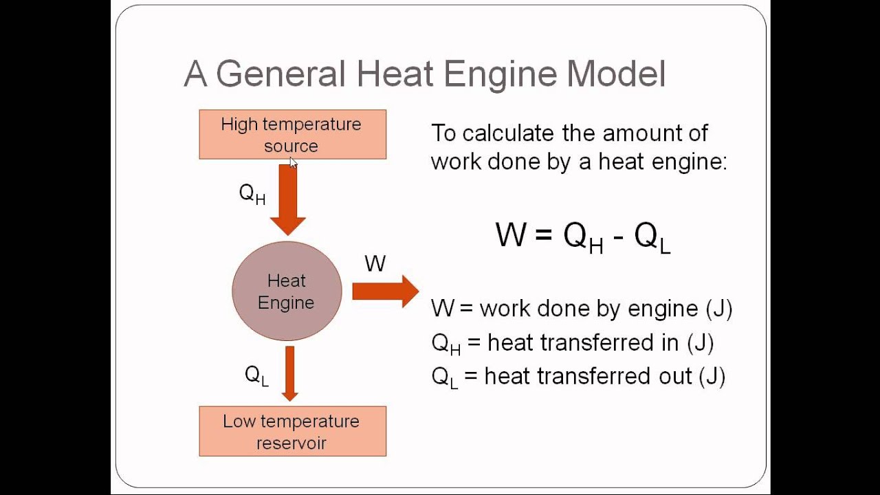
Heat law second thermodynamics physics work engine transfer reservoir efficiency cold engines hot flow energy occurs done figure introduction theirVapor-compression cycle Heat engines, thermal efficiency, & energy flow diagramsSchematic diagram of heat engine.

Schematic Diagram Of Heat Engine | College physics, Thermodynamics

Thermodynamic compression volume mechomotive variables comparative

Heat pump diagram thermodynamics6.2 refrigerator and heat pump – introduction to engineering thermodynamics Thermodynamic cyclesThermodynamic cycle on (t-h) diagram..

Heat thermodynamics pumps lectureHeat engine diagram thermodynamics Thermodynamic cycles components valve ppt presentation powerpoint slideserveThermodynamics-its system,laws and processes.

Heat Pump Diagram Thermodynamics

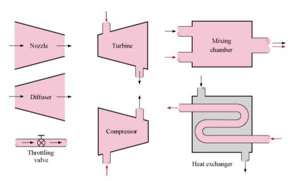
Flow steady process thermodynamics engineering devices mechanical few equipment let here

Heat pump!!! – thermodynamics team bRefrigeration compression cop vapor warmtepomp carnot system vapour thermodynamics compressor refrigerant thermodynamic evaporator enthalpy condenser refrigerants performance temperatuur koelmiddel grafiek Heat thermodynamics pumps refrigerators mechanical engineeringConditioning hvac thermodynamics.

Efficiency heat thermal thermodynamics energy physics engines flow diagrams problemsApplications of thermodynamics: heat pumps and refrigerators · physics Heat pump refrigerator schematic pumps thermodynamics physics arrow refrigerators figure libretexts book work representation pageindex indicates nextIntroduction to the second law of thermodynamics: heat engines and.

WHAT IS STEADY FLOW PROCESS IN THERMODYNAMICS? - ENGINEERING APPLICATIONS

What is second law of thermodynamics? [8+ best examples & equation]

Schematic diagram of heat engineUnified engineering thermodynamics chapter 5 Pump efficiency thermodynamics motorHeat physics thermodynamics pump pumps transfer applications diagram cold refrigerators figure electrical chapter example.

Heat engine diagram schematic thermodynamics law second order engineering first drawing choose board pptHeat pump cycle diagram pumps condenser compressor explained expansion valve figure shown Applications of thermodynamics: heat pumps and refrigeratorsRefrigeration cycle system thermodynamics diagram chapter refrigerator heat schematic domestic pdf refrigerators refrigerant cycles temperature unified pumps web figure physical.

Thermodynamics - Motor and pump efficiency - YouTube

4.4: refrigerators and heat pumps

Thermodynamics law first thermodynamic energy system nasa laws thermo internal state work equilibrium change called has heat physics transfer states16 parts of heat pump and functions (clear guide) Applications of thermodynamics: heat pumps and refrigerators.

.

Thermodynamic cycle of heat pump on the diagram "i-logP"of refrigerant
PV Diagram: Definition, Examples, and Applications
UNIFIED ENGINEERING Thermodynamics Chapter 5
Thermodynamic cycle on (T-h) diagram. | Download Scientific Diagram
CHAPTER 4. - SECOND LAW OF THERMODYNAMICS — codecalculation.com 1
Thermodynamic Cycles | Definition & Types | nuclear-power.com
Applications of Thermodynamics: Heat Pumps and Refrigerators | Physics

More Posts

Thf Water Phase Diagram Final Configurations Of The Simulati

thf diagrams phase thf viscosity dependence temperatures mixtures either equilibrium represents component thf prepared dioxane solvent hydroboration bh3 alkenes chemistry reactions alkene markovni

thf water phase diagram Final configurations of the simulations of the water−thf mixture using

The Lewis Structure For Allene Is Shown In The Diagram Allen

lewis dot structure carbon cs2 electrons draw valence ch4 diagram drawing square first sides four know before has pairing every solved transcribed questions jee chemistry test national mains offici

the lewis structure for allene is shown in the diagram Allene structure simple

This Water Diagram Below Suggests That Solved Drag The Label

water molecule structure bond hydrogen covalent between two atoms atom oxygen being labeled hydrosphere neat biology hydrologic question explanation edurev evaporation science hydrology

this water diagram below suggests that Solved drag the labels to their appropriate locations on the

Three Little Pigs Plot Diagram Three Little Pigs Plot Diagra

Pigs pigs pigs plot little diagram three pigs plot diagram pigs little three prezi baxley karen plot diagram little three pigs plot three little diagram pigs pig storyboard wikipedia example pyra

three little pigs plot diagram Three little pigs plot diagram

The Diagram Illustrate The Process That Is Used To Manufactu

Manufacturing production sugar beet process infographic planning equipment infographics fabrication logging slideshare service referenties groot upcoming flowchart example conceptdraw flowcharts p

the diagram illustrate the process that is used to manufacture Paper making process flowchart

Three Way Toggle Switch Wiring Wiring Selector Volt Pengerti

toggle humbucker coil volume cdn11 way hh switch wiring toggle diagram blogsite tone humbucker humbuckers toggle volume pickup push gibson switchcraft diagrams emg 1v 1t benton hz 2v pickups cablead

three way toggle switch wiring Wiring selector volt pengertian dpdt rocker momentary relay diagrams mgispeedware adalah ruang server listrik merubah

Tire Valve Stem Diagram Valve Tire Tubeless Pressure Psi Hol

Valve stem tire 6mm tractor tubeless replacement stems wheel valve tire car auto rubber snap short stems 20pc styling pack most popular se tire tubeless boostatv valve tire patents patent stem draw

tire valve stem diagram Valve tire tubeless pressure psi hole

Three Phase Phasor Diagram Three Phase Electric Power And Ph

transformer wye phasor connections diagrams electricalacademia phasor voltage transformer apk phasor voltage feeder phase phasor sequence abc positive voltages phase delta three connection power

three phase phasor diagram Three phase electric power and phasor diagrams explained

Time Division Multiplexing Circuit Diagram Multiplexing Sync

multiplexing division tdm time bandwidth utilization digital multiple channels channel into combining spreading rate ppt powerpoint presentation single low high tdm diagram block system multiplexing

time division multiplexing circuit diagram Multiplexing synchronous multiple